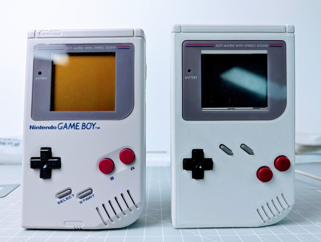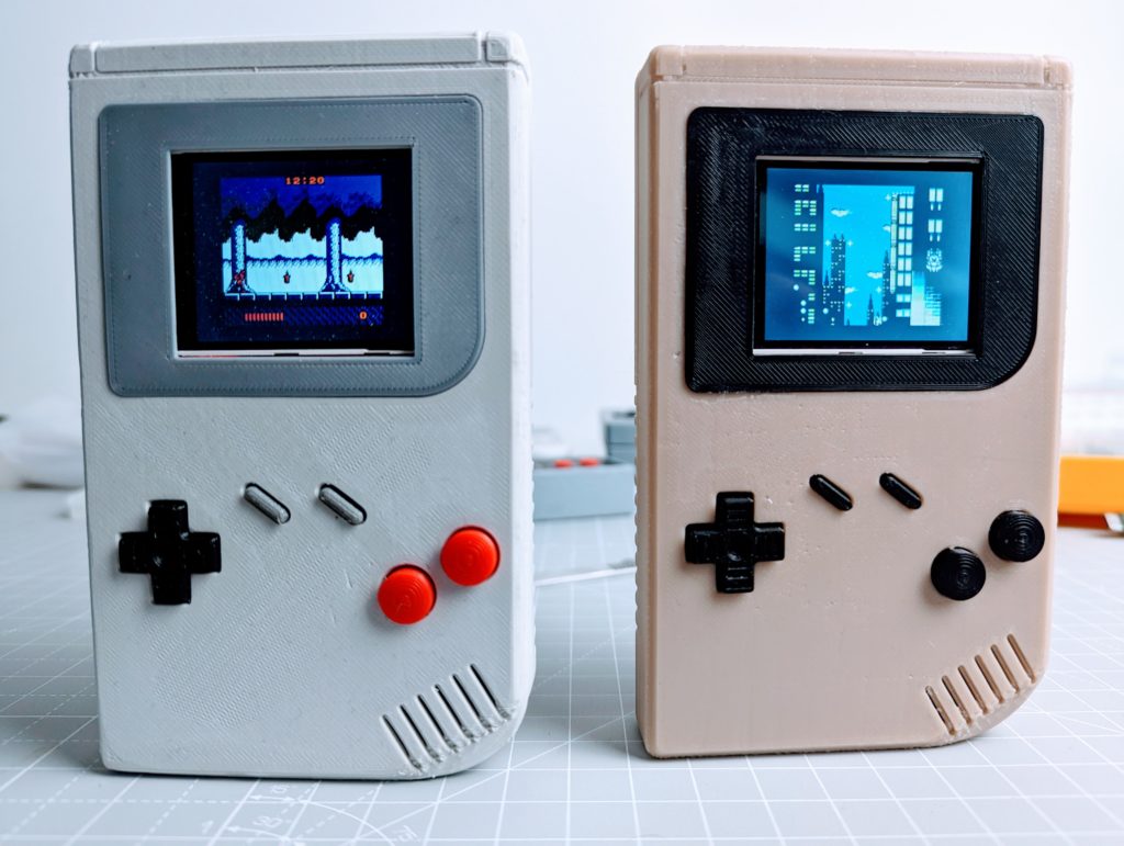
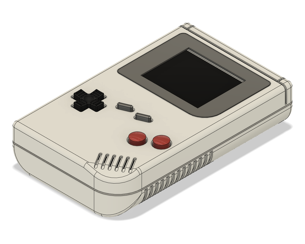
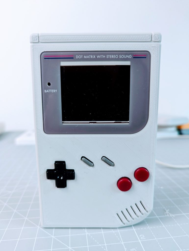
Pico-GB is a 3d printed GameBoy emulator handheld gaming console for Raspberry Pi Pico that ressembles to the original Nintendo Game Boy released in 1989.
This homemade Game Boy emulator is a fun and creative way to bring back old games on the beloved classic Game Boy console. With just a few basic components and a little bit of tinkering and programming you can build your own handheld gaming console capable of playing original Game Boy titles.
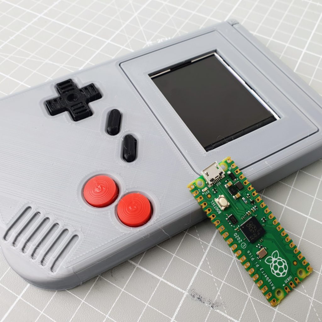
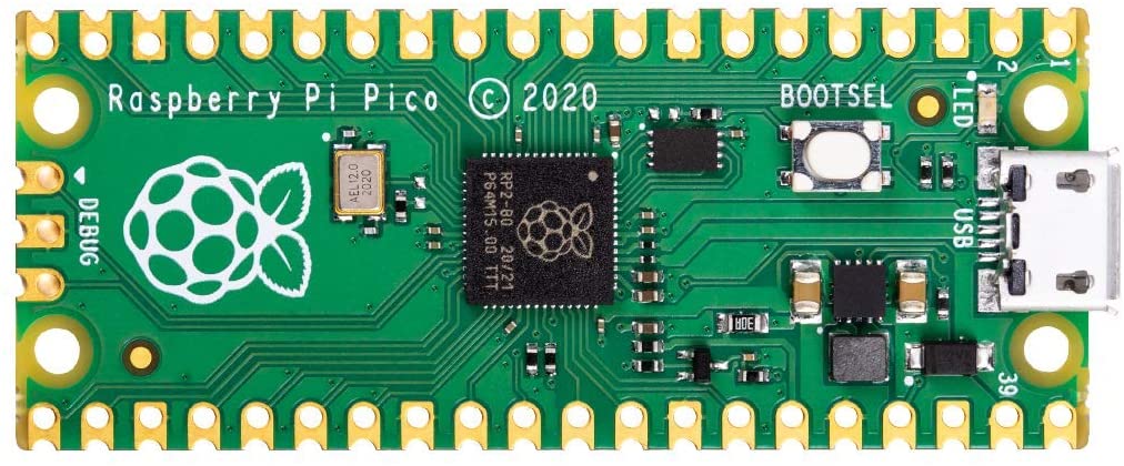
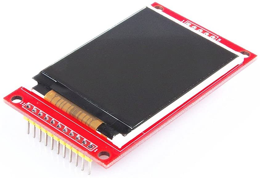
All you need is a Raspberry Pi Pico, an ILI9225 LCD display, an SD card and a couple of micro-push buttons to get started!! With a few hours and some basic soldering skills, you can build yourself a beautiful handheld Game Boy emulator to play all your favorite classic games. So, if you’re feeling nostalgic for some good old fashion Game Boy gaming then building a homemade emulator handheld is a great and inexpensive way to do just that!
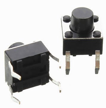
Pico-GB is based on the $4 Raspberry Pi Pico microcontroller. The case and buttons are 3D printed. The screen is a 2.2-inch LCD with a resolution of 220×176 pixels and 65K colors. There are 8 buttons: 4 for the DPAD + 4 action buttons (A, B, select, start). The buttons are 6x6x6mm micro push buttons.
The Game Boy emulator used by Pico-GB is Peanut-GB by Mahyar Koshkouei (deltabeard) with some changes done by me to support sound and accommodate SD card menu/save games on Raspberry Pi Pico.
What you need
To make Pico-GB, you will need the parts below:
Recommended tools
| 3D Printer (e.g. Creality Ender 3 V2) |  |
| Soldering Station (e.g. Yihua 939D+ III) |  |
| Set of 4 hexagonal screwdrivers (1.5 mm, 2mm, 2.5mm and 3mm) |  |
| Digital Multimeter |  |
Electronics
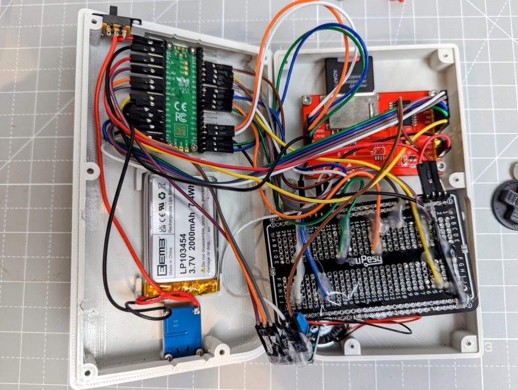
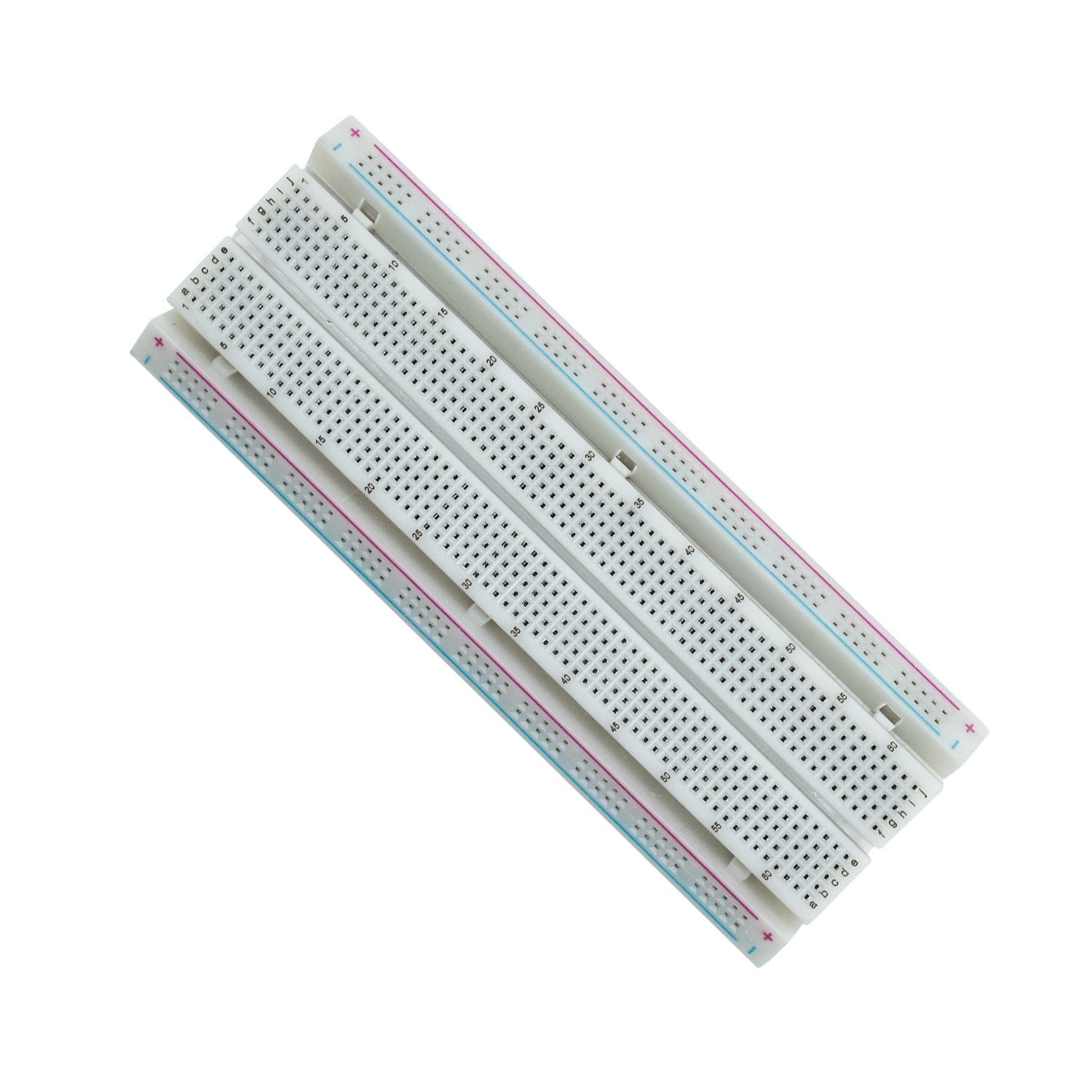
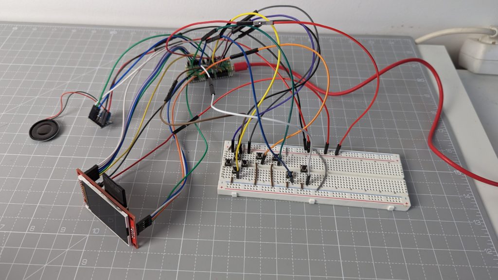
The Pico-GB GameBoy emulator can be built entirely on a breadboard! No soldering required. This is useful for testing and if you don’t have a 3d printer.
The diagram below shows how everything is connected to the Raspberry Pi Pico. Note that the 3V3 (OUT) pin is used to power the LCD display and the MAX98357A amplifier.

Flashing the firmware
The Game Boy emulator used by Pico-GB is Peanut-GB by Mahyar Koshkouei (deltabeard) with some changes done by me to support sound and accommodate SD card menu/save games on Raspberry Pi Pico.
It’s easier to flash the firmware before starting the assembly so you can test that everything is working as expected at every stage of the build:
- Download the latest .UF2 file from the release page
- Push and hold the BOOTSEL button on the Pico, then connect to your computer using a micro USB cable. Release BOOTSEL once the drive RPI-RP2 appears on your computer.
- Drag and drop the .UF2 file on to the RPI-RP2 drive. The Raspberry Pi Pico will reboot and will now run the emulator.
Pico-GB Assembly
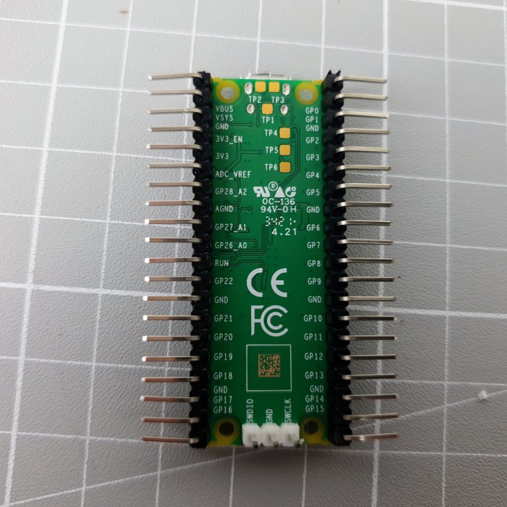
Soldering the headers
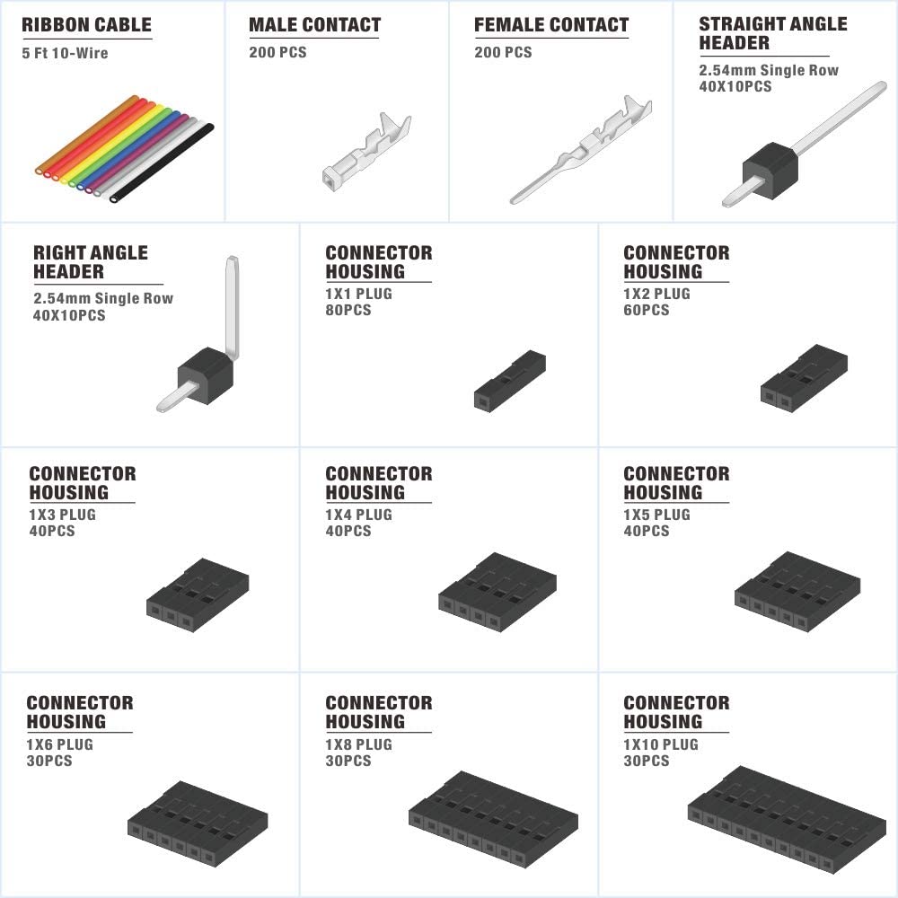
For this project, you will need to attach two 20-pin 2.54mm right angle male headers to your Raspberry Pi Pico. You can also solder the wires directly.
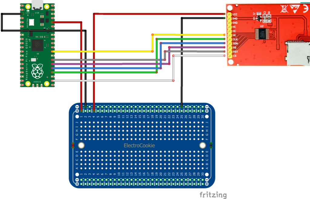
Connecting the display
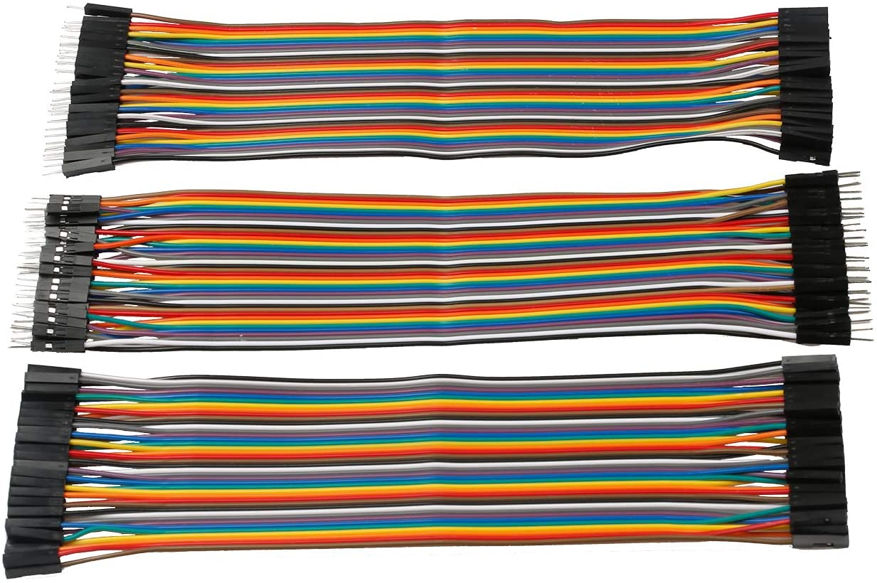
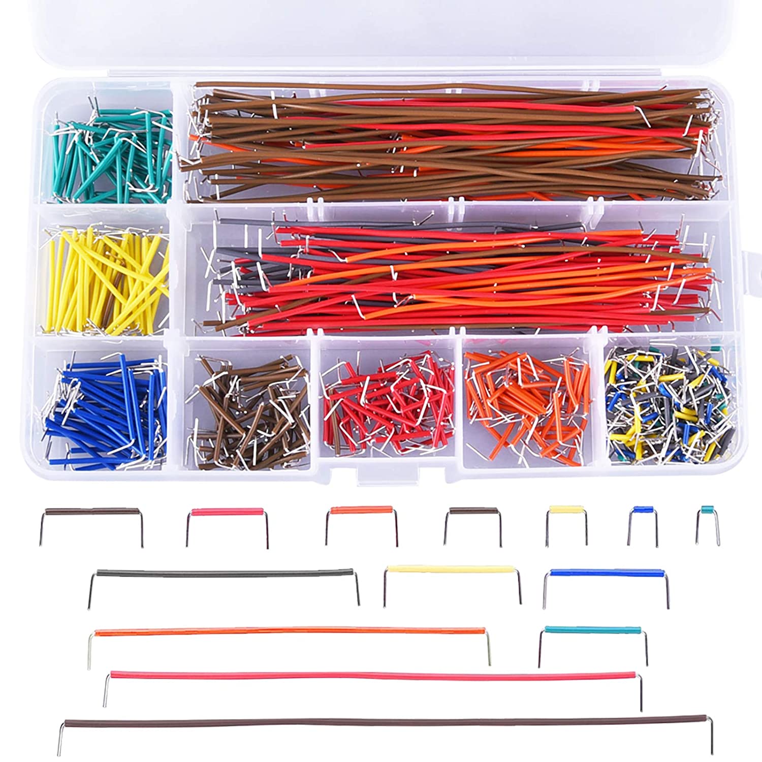
Connect the ILI9225 display to the Pico with ~20cm long wires with Dupont Female connectors as shown below:
- LCD VCC = +3.3V (OUT) = RED
- LCD GND = GND = BLACK
- LCD CS = GP17 = WHITE
- LCD CLK = GP18 = GREEN
- LCD SDI = GP19 = BLUE
- LCD RS = GP20 = PURPLE
- LCD RST = GP21 = GREY
- LCD LED (when present) = GP22 = YELLOW
Note) Not all ILI9225 displays have a LED pin. However, if a LED pin is present, it must be connected to +3.3V or to a positive voltage between 0 and 3.3V (to adjust the brightness) otherwise the display won’t display anything
Note) The display VCC pin is not directly connected to the +3.3V pin of the Pico because there is only one 3.3V output on the Pico but we need to power multiple devices with 3.3V (ILI9225 LCD display + MAX98357 power amplifier module)
CAUTION) Not too many things can burn your Pico or your computer, but always check your connections twice. In particular, always check that there is no short between the +3.3V pin and the ground pin!
Preparing the SD Card
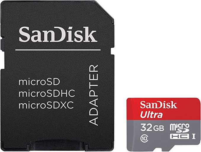
The SD card is used to store game ROMs and save game progress. For this project, you will need a FAT 32 formatted Micro SD card with roms you legally own. Roms must have the .gb extension. All roms must be copied to the root folder.
- Insert your SD card in a Windows computer and format it as FAT 32
- Copy your .gb files to the SD card root folder (subfolders are not supported at this time)
- Insert the SD card into the ILI9225 SD card slot using a Micro SD adapter
- No copyrighted games are included with Pico-GB / RP2040-GB: You can use open source roms with Pico-GB for example Libbet and the Magic Floor GB by Damian Yerrick
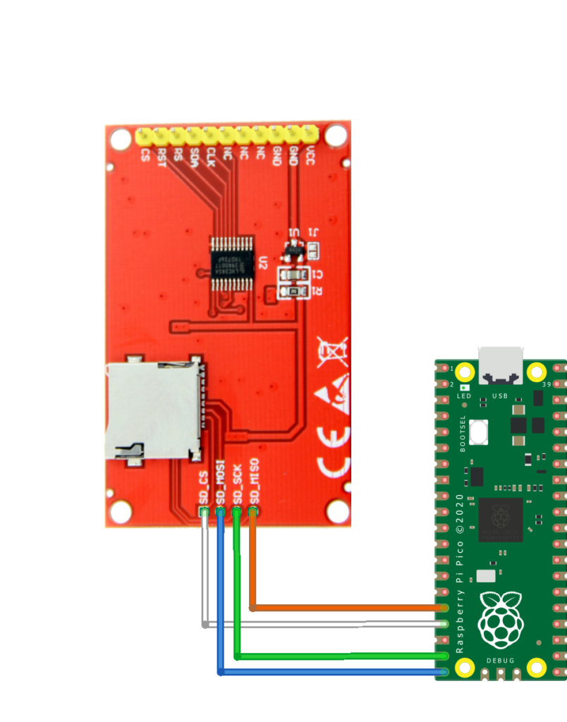
Connecting the SD Card Reader
- SD MISO = GP12 = ORANGE
- SD CS = GP13 = WHITE
- SD SCK = GP14 = GREEN
- SD MOSI = GP15 = BLUE
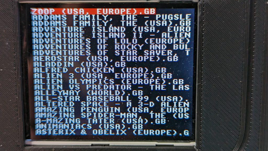
The ILI9225 sd card reader does not always function properly. When this happens, the Pico cannot communicate with the device and displays random characters instead of game names:
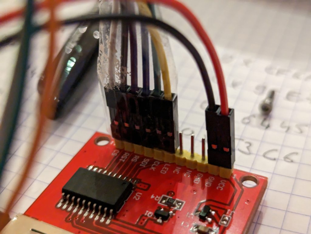
In that case, you can directly connect the sd card adapter to the Pico as shown below. In addition to the white/blue/green/orange wires shown, you need to connect the SD card to the Pico 3.3V (red wire) and to GND (black wire):
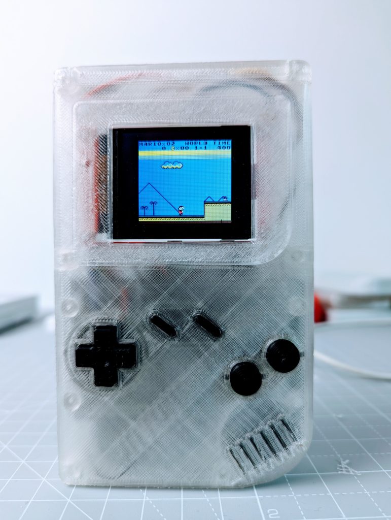
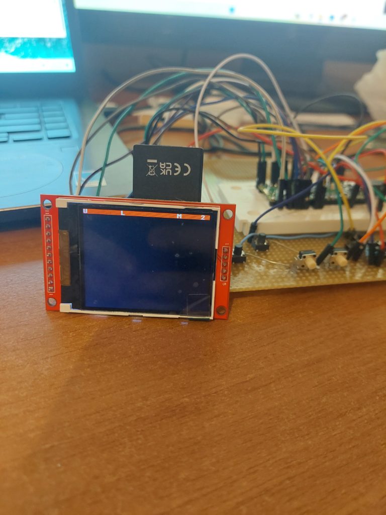
After connecting the display and the sd card reader to the Pico, you can check that your screen works correctly by connecting your Pico to USB. If everything works as expected, you should see the game selection menu!
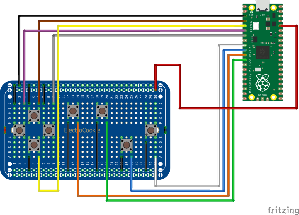
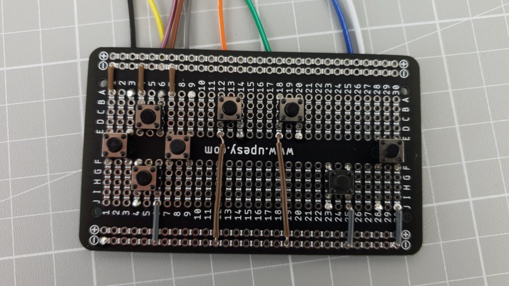
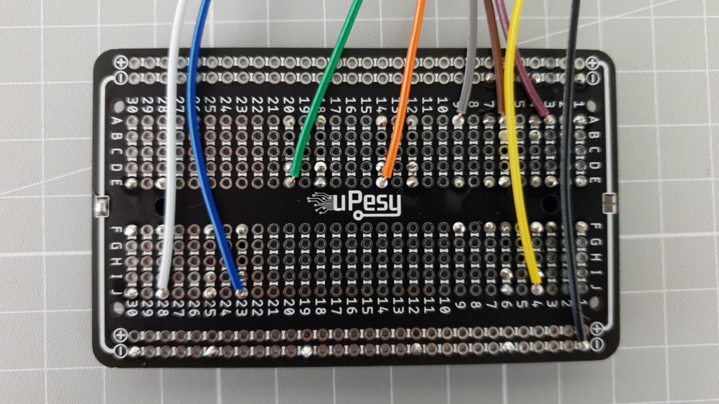
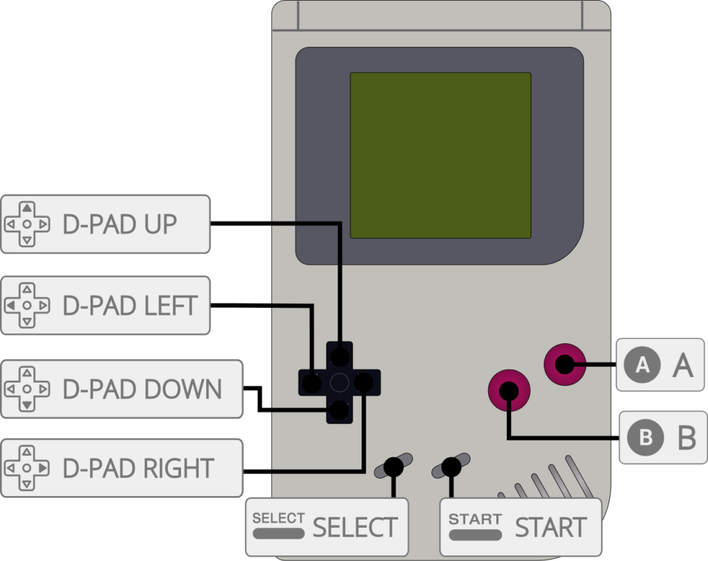
Connecting the buttons
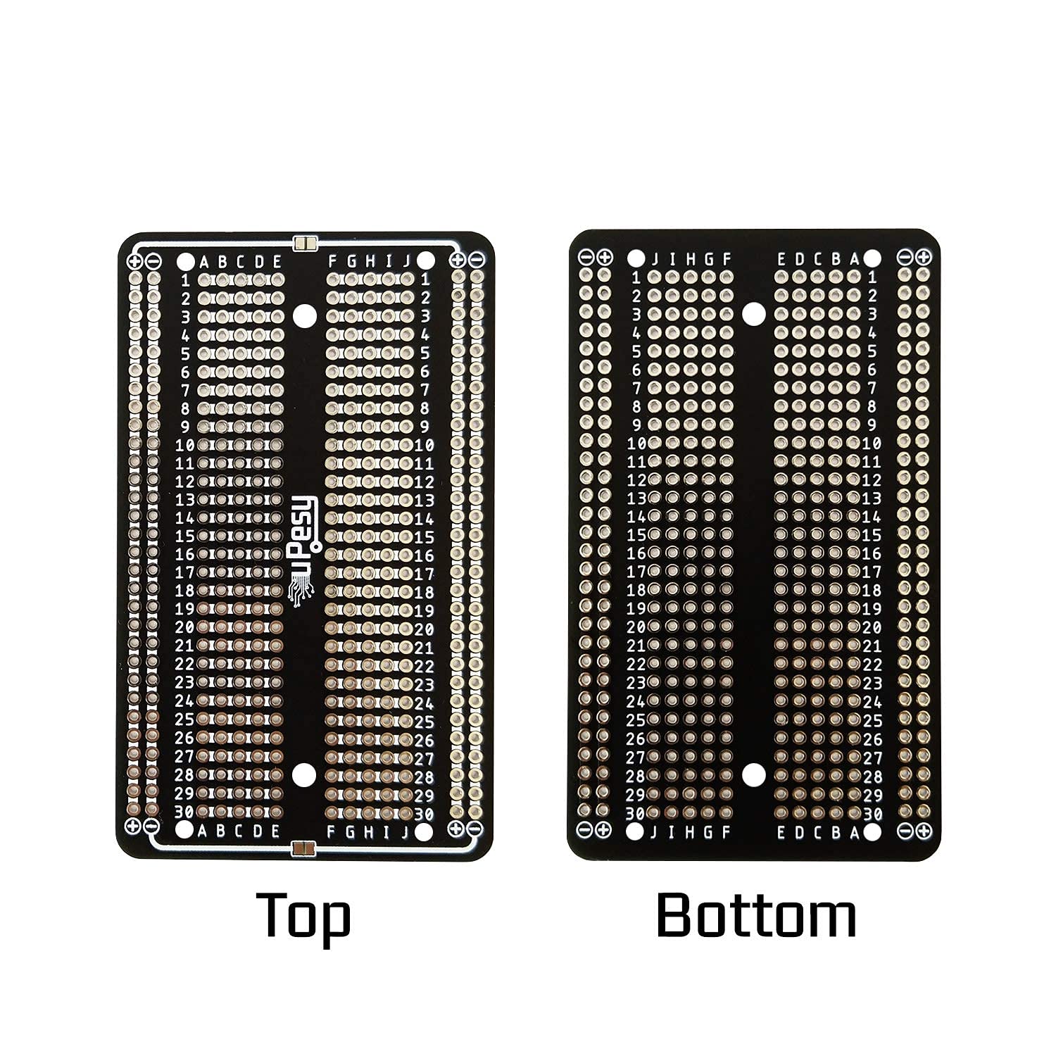
Solder the push buttons to the solderable breadboard as shown on the image below. Each button is connected to GND on one side and to the Raspberry Pi Pico on the other side. To connect the buttons to the Raspberry Pi Pico, I use ~20 cm wires with a female Dupont connector on one side.
- UP = GP2 = BROWN
- DOWN = GP3 = YELLOW
- LEFT = GP4 = PURPLE
- RIGHT = GP5 = GREY
- BUTTON A = GP6 = WHITE
- BUTTON B = GP7 = BLUE
- SELECT = GP8 = ORANGE
- START = GP9 = GREEN
- BUTTONS GND = GND = BLACK
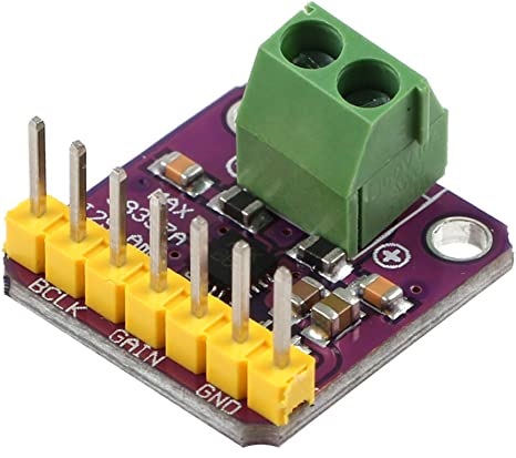
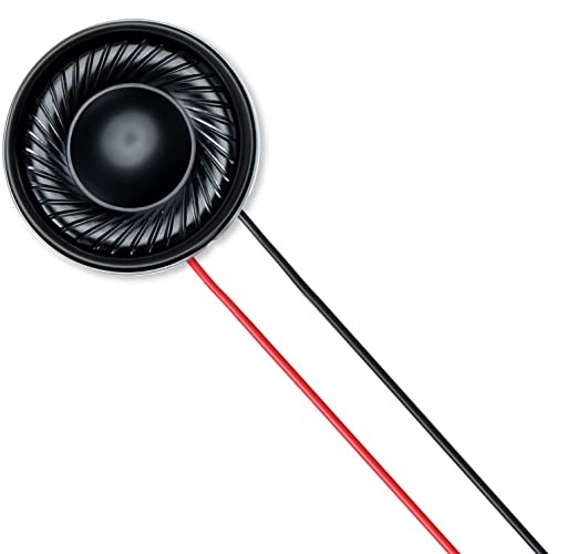
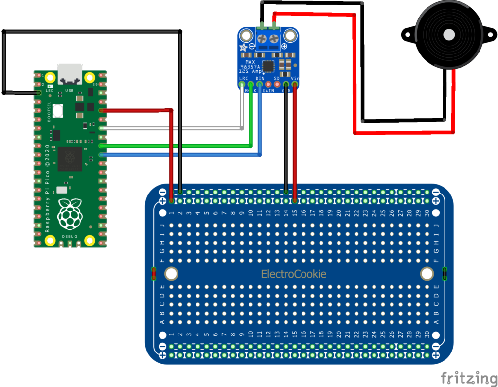
Adding sound
Connect the MAX98357 amplifier to the Pico using ~20cm wires with Dupont female connectors and the speaker to the amplifier as shown below. As there is only one 3V3 output on Raspberry Pi Pico which must be shared between the LCD display and the sound amplifier, you can use the (+) line on the top of the solderable breadboard to distribute the 3.3V to all boards. Connect the 3.3V output of the Raspberry Pi Pico to the (+) line of the breadboard then connect each component that needs 3.3V to this (+) line.
- MAX98357A DIN = GP26 = BLUE
- MAX98357A BCLK = GP27 = GREEN
- MAX98357A LRC = GP28 = WHITE
- MAX98357 GND = GND = BLACK
- MAX98357 VIN = 3V3 (OUT) = RED
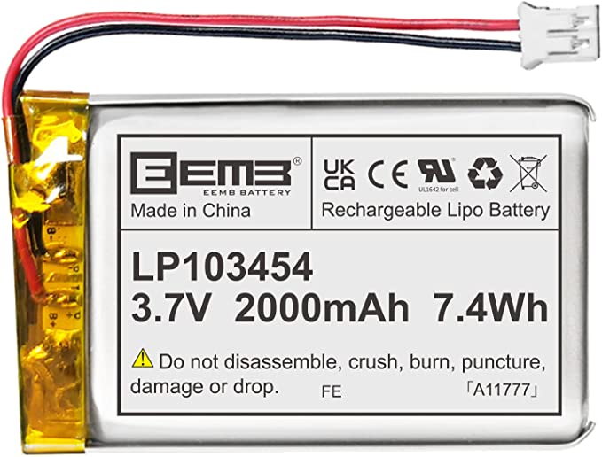
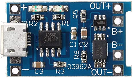
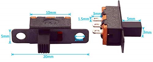
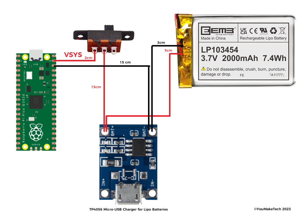
Connecting the battery and charger (optional)
You can play your Pico-GB by simply connecting it to USB. However, if you want to use your Pico-GB anywhere and make it a portable handheld game console, you can add a Lipo battery + a on/off switch + a USB charger. As the power consumption of the Pico (even overclocked to 266MHz) is very low, this gives days of autonomy!
Note) The preferred way to provide power for Raspberry Pi pico when it is not connected to USB is to provide a voltage between between 1.8 and 5.5V to the VSYS pin.
CAUTION) Do not turn on the battery when the Pico is already connected to a power source via its micro USB connector. I kept the power circuit very simple but it should normally include a Schottky diode to prevent problems if you also supply power to the VBUS pin.
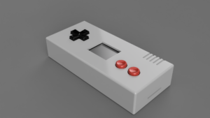
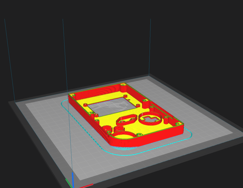
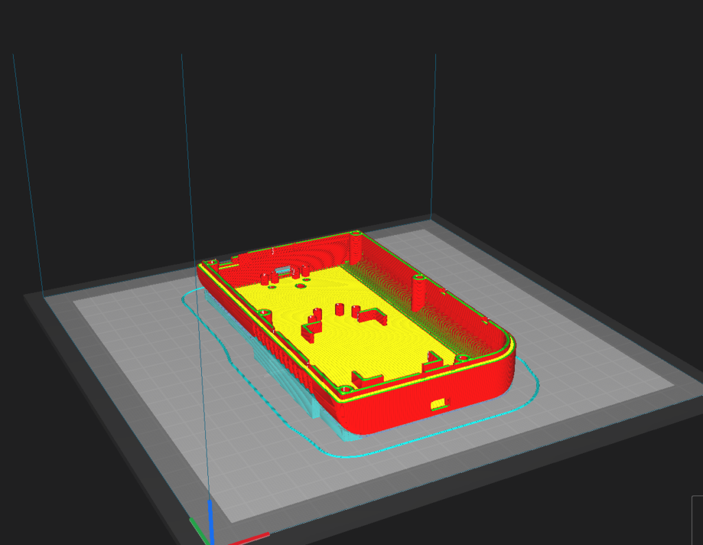
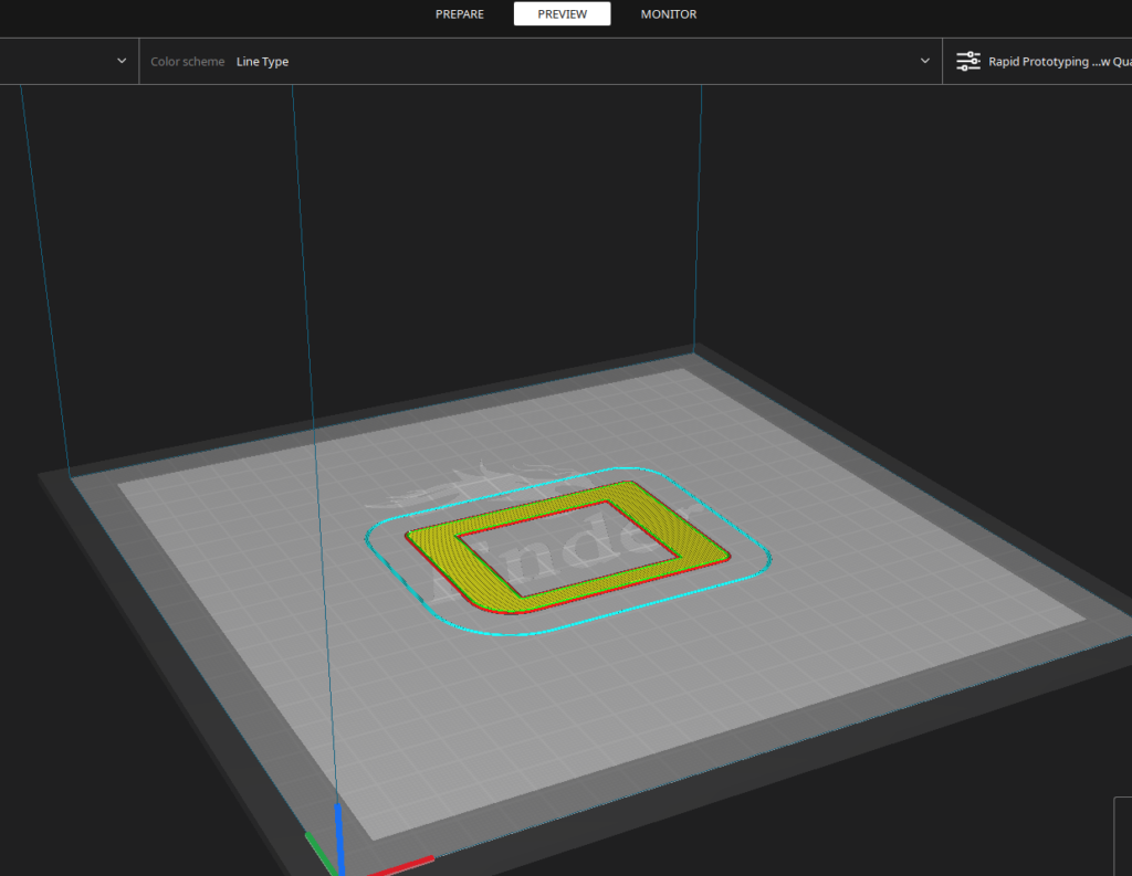
3D Printing
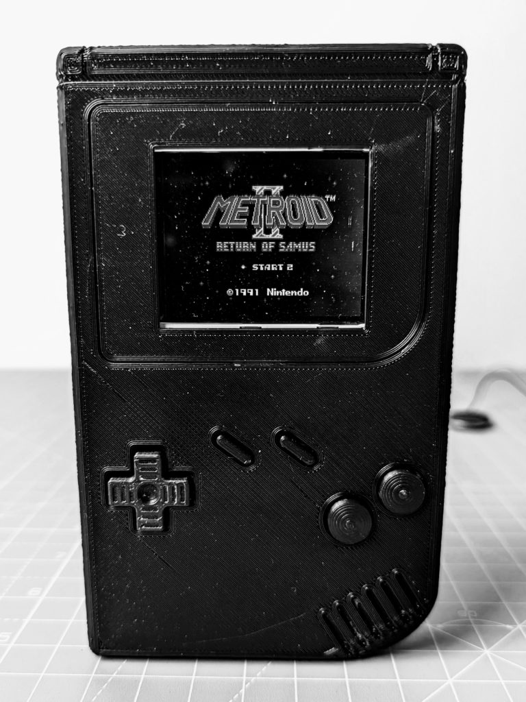
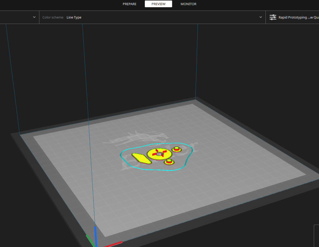
All parts are printed in PLA/PLA+ except for the pads which are printed in TPU. I print the shell with “Rapid prototyping” print settings and the buttons with “Super Quality” print settings. Because they are small parts, the buttons benefit from a small layer height (e.g. 0.12mm) to achieve the best quality. Alternatively, you can print the buttons in TPU for a softer feel.
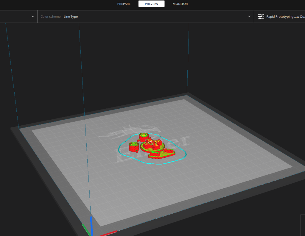
Under the buttons, like on the original Game Boy, there are elastic pads to improve the feeling of pressing the buttons. They are printed in TPU with these print settings. TPU is notoriously difficult to print. The secret is to print slowly (20mm/s) + slow down the retractions or disable them completely (with a Bowden system) + keep the build plate at room temperature (TPU adheres very strongly, no need to heat the build plate). If you don’t want to use TPU, you can print them in PLA, the buttons will just feel a little bit less qualitative (more noise + less rebound).
Pico-GB Controls
SD Card Game Selection Menu Controls
| D-PAD UP/DOWN | Next/previous item in the menu |
| D-PAD LEFT/RIGHT | Next/previous page |
| A or B | Flash and start the game |
| START | Start the last game from flash (without rewriting, preserve the flash memory) |
In-Game Controls
| SELECT+START | Resets back to the SD card menu. Game saves are saved to the SD card. |
| SELECT+UP/DOWN | Increase/decrease sound volume |
| SELECT+RIGHT/LEFT | Switch between manual color palettes |
| SELECT+A | Enable/disable fast-forward |
Known issues and limitations
- No copyrighted games are included with Pico-GB / RP2040-GB. For this project, you will need a FAT 32 formatted Micro SD card with roms you legally own. Roms must have the .gb extension.
- The RP2040-GB emulator is able to run at full speed on the Pico, at the expense of emulation accuracy. Some games may not work as expected or may not work at all. RP2040-GB is still experimental and not all features are guaranteed to work.
- RP2040-GB is only compatible with original Game Boy DMG games (not compatible with Game Boy Color or Game Boy Advance games)
- Repeatedly flashing your Pico will eventually wear out the flash memory (Pico is qualified for min. 100K flash/erase cycles)
- The emulator overclocks the Pico in order to get the emulator working fast enough. Overclocking can reduce the Pico’s lifespan.
- Use this software and instructions at your own risk! I will not be responsible in any way for any damage to your Pico and/or connected peripherals caused by using this software. I also do not take responsibility in any way when damage is caused to the Pico or display due to incorrect wiring or voltages.
Programming Games in MicroPython
Pico-GB can be used to program your own games in MicroPython or in C. See for example Tetris in MicroPython for Pico-GB
Makes