Make your own retro game console with a Raspberry Pi Pico and program a simple game of Pong in MicroPython!
- Overview
- What you need
- 3D Printing
- Source code & games for the Raspberry Pi Pico Retro Gaming System
- Installing MicroPython on Raspberry Pi Pico
- “Hello World” in MicroPython
- Using an I2C SSD1306 OLED display with Raspberry Pi Pico
- Game programming on Raspberry Pi Pico | Pong
- Pong game on Raspberry Pi Pico | Adding buttons to move the paddle
- Making sounds with a piezo buzzer on Raspberry Pi Pico
- Making the complete console
Overview
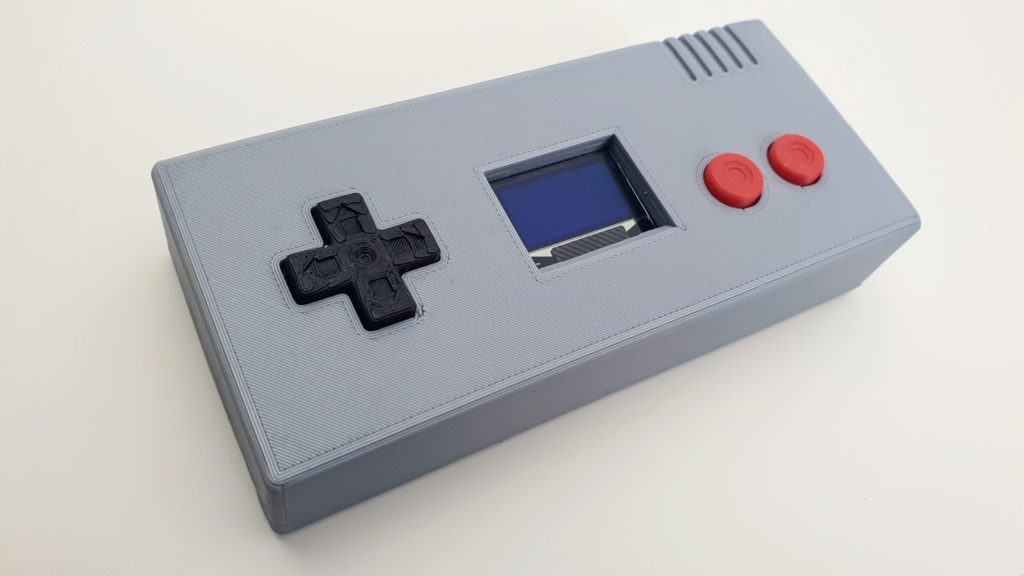
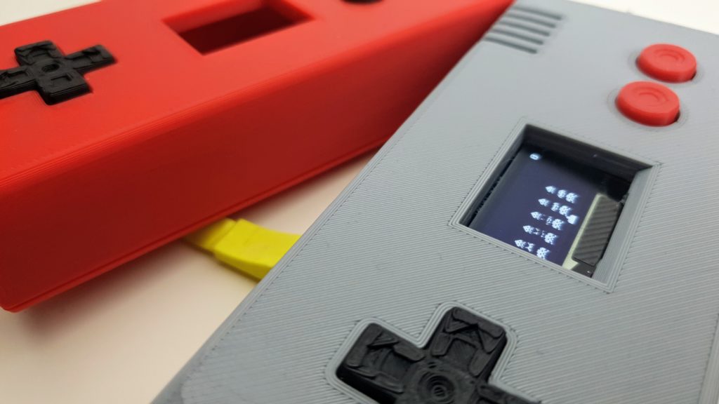
Today, we make the Raspberry Pi Pico RetroGaming System, a simple game console you can build on a breadboard! For less than $20, you can make your own game console and start coding games! Retro games are probably the funniest way to learn to program!
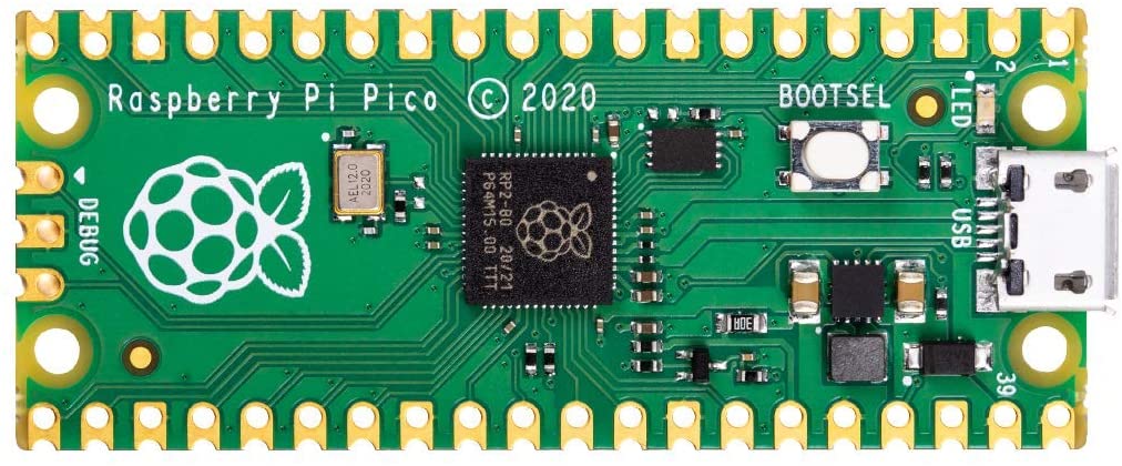
The Pi Pico Retro Gaming System is a DIY game console based on the $4 Raspberry Pi Pico microcontroller. The Raspberry Pi Pico Retro Gaming System can be programmed in MicroPython, a special version of Python made for Microcontrollers, or in C++ for better performance. The Raspberry Pi Pico is great for many DIY projects. The Pico makes programming in Python fun and simple.
| Size | 128x57x27mm |
| Screen | 0.96in SSD OLED (27x20mm) |
| Display size | 27x20mm |
| Resolution | 128×64 pixels |
| Colors | Monochrome |
| Power | USB |
| Inputs | Eight-way control pad 2 action buttons (A, B) |
| CPU | Raspberry Pi Pico RP2040 133MHz dual ARM Cortex-M0+ cores |
| Memory | 264KB RAM + 2MB Flash |
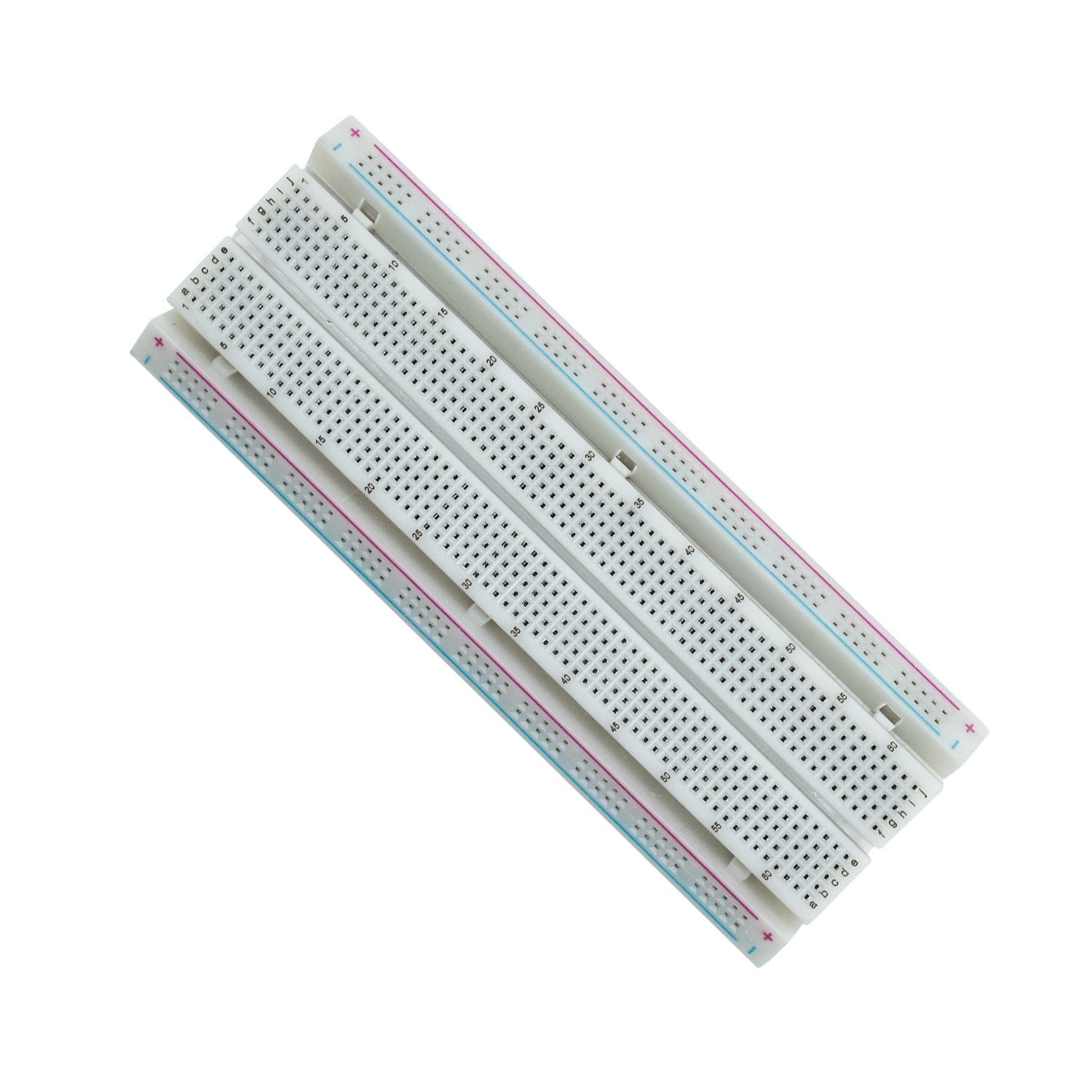
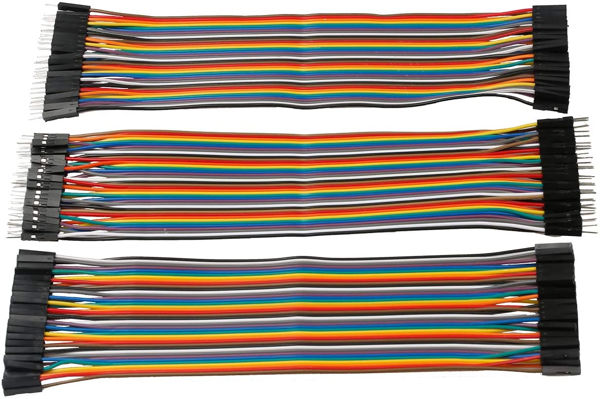
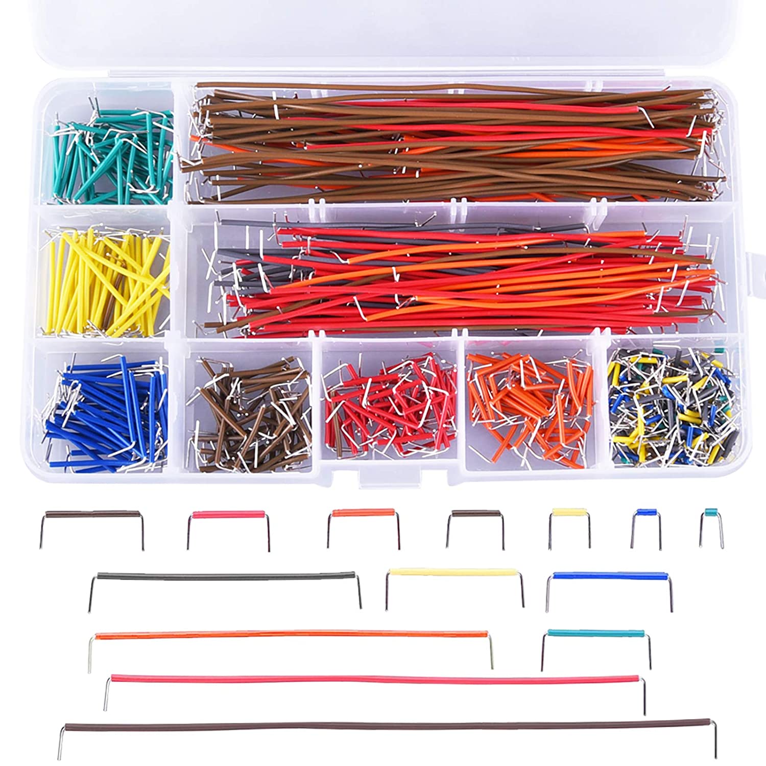
What you need
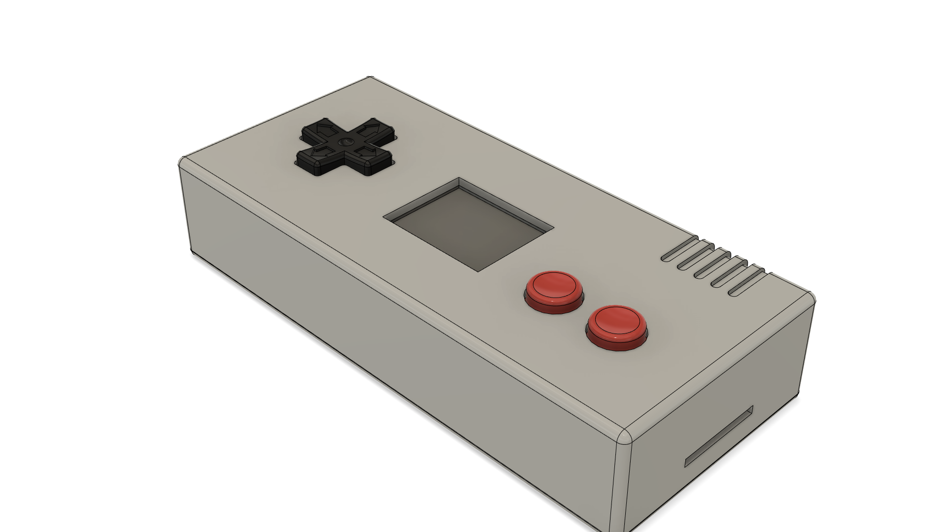
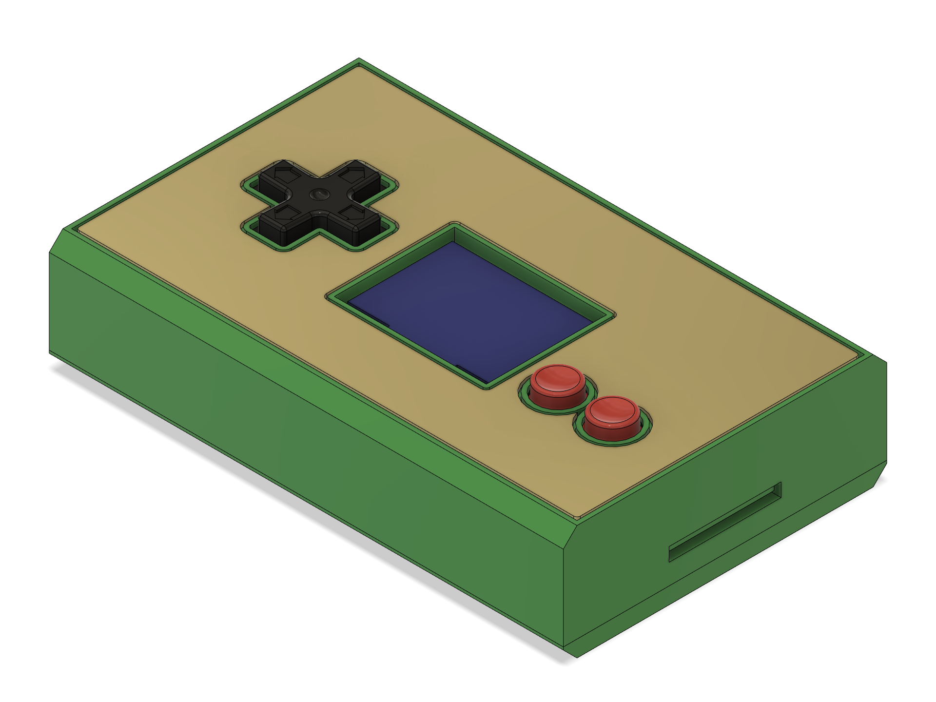


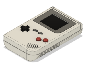
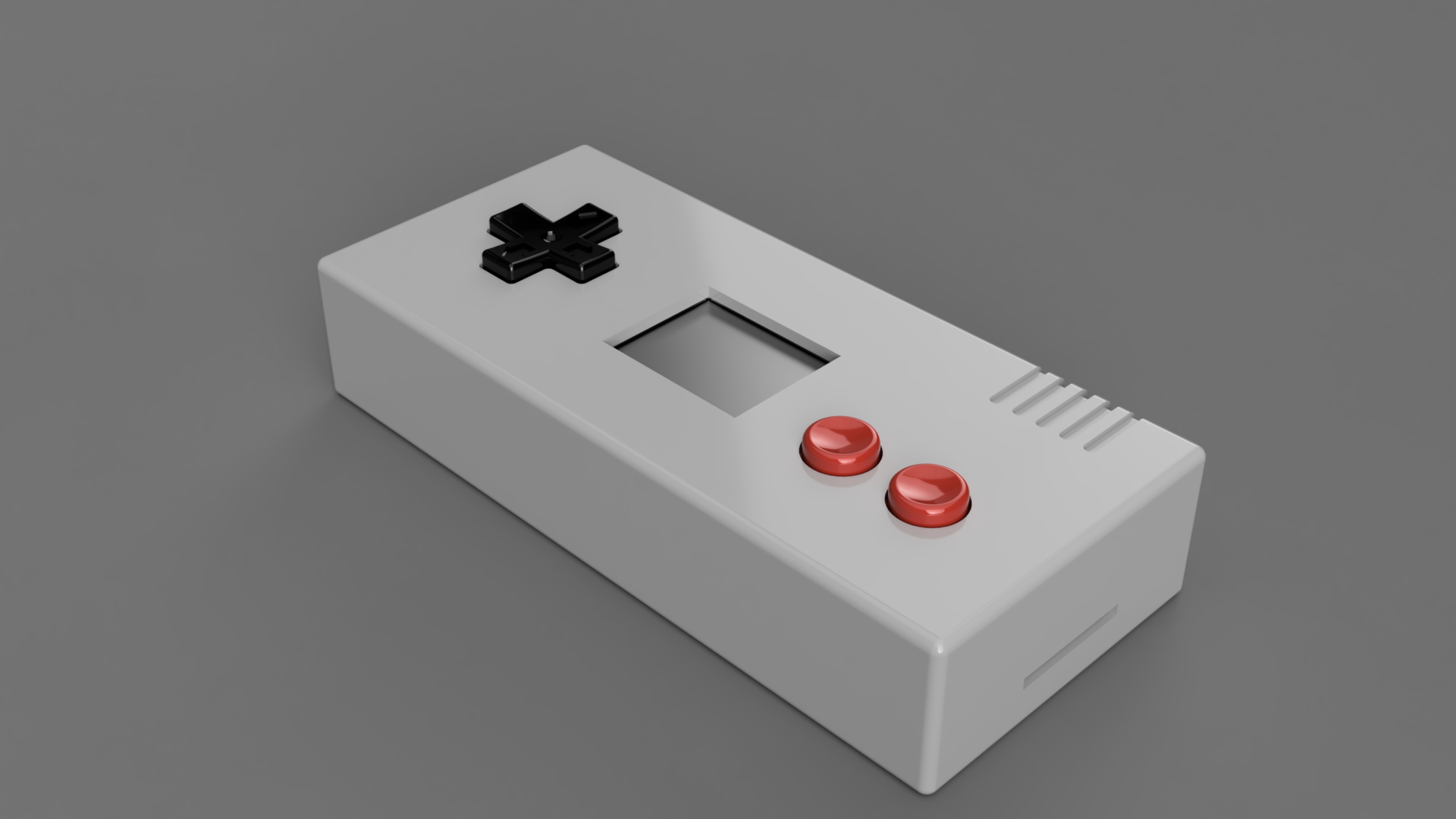
3D Printing
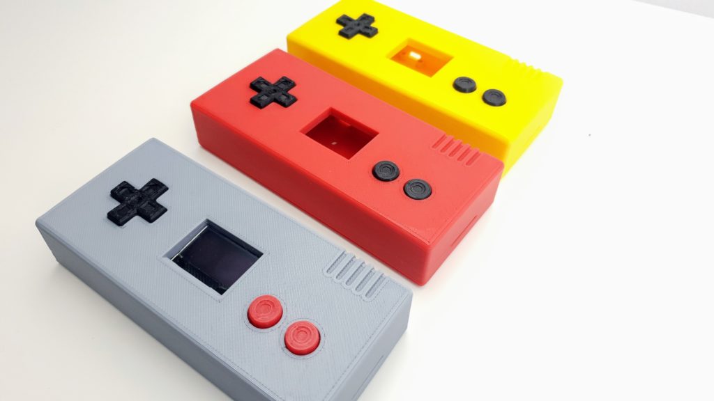
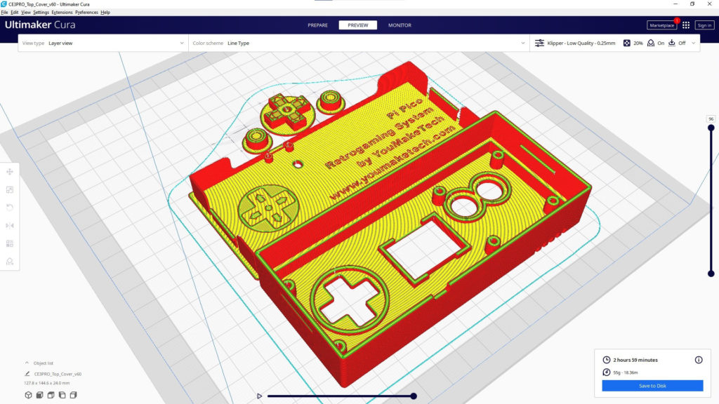
You can build the game console on a breadboard but if you have a 3d printer, you can print the case and the buttons for the Pi Pico Retro Gaming System.
Download the parts
Print Settings
I printed these parts in Sunlu PLA+. My print settings (Ultimaker Cura):
- Layer Height: 0.25 mm
- Line Width: 0.4 mm
- Wall Thickness: 0.8 mm (=2 walls)
- Top/Bottom Thickness: 0.75 mm (=3 layers)
- Infill Density: 20%
- Infill Pattern: Cubic
- Printing Temperature: 230 deg C
- Build Plate Temperature: 70 deg C
- Enable Print Cooling: Enabled
- Fan Speed: 100%
- Initial Fan Speed: 0%
- Regular Fan Speed at Layer: 2
- Generate Support: Disabled
Print Orientation
Source code & games for the Raspberry Pi Pico Retro Gaming System
Download code and games for the Raspberry Pi Pico RetroGaming System on GitHub
Installing MicroPython on Raspberry Pi Pico
Before you can start to program Pico with MicroPython, you will need to install Thonny on your computer and MicroPython on your Raspberry Pi Pico. Thonny is a beginner friendly Python IDE (Interactive Development Environment).
- Download and install Thonny on your computer
- Start Thonny and click on the bottom right corner of the window, then click on “Configure interpreter…”
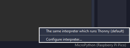
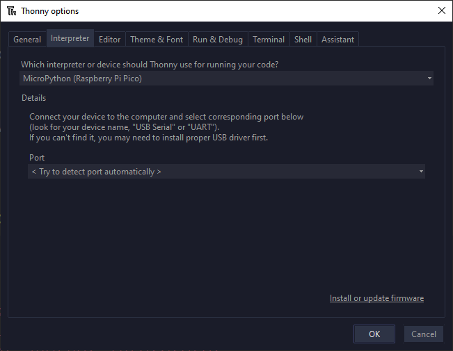
- Select MicroPython (Raspberry Pi Pico) and <Try to detect port automatically>
- Connect your Pico to your computer while maintaining the BOOTSEL button (The white button on top of the Raspberry Pi Pico)
- Click on “Install or update firmware” on the bottom right corner of the previous window. This opens a new window:
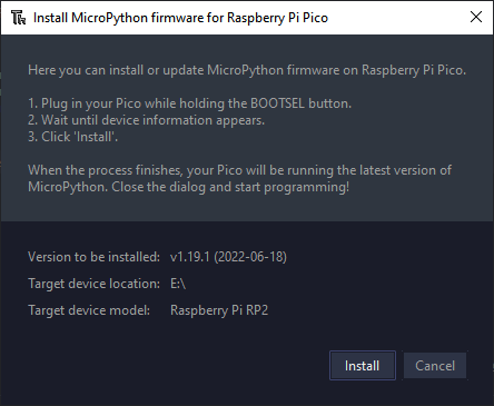
- Click on Install
“Hello World” in MicroPython
If everything has worked correctly, you should see the Micropython shell at the bottom of Thonny:
In the shell, you can interactively send python commands to Pico and see the result immediately. This is what makes programming in MicroPython so much easier than in C (e.g. Arduino)!
Let’s give it a try!
The onboard LED on Raspberry Pi Pico is connected to GPIO pin 25. You can blink this on and off interactively. To control hardware, you first import Pin from the machine module. You specify that GPIO pin 25 is a digital output:
from machine import Pin
led = Pin(25, Pin.OUT)
To turn the LED on, set the pin value to one:
led.value(1)The green led on the top of Pico should turn on.
You can turn it off again by setting the pin value to zero:
led.value(0)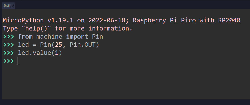
Using an I2C SSD1306 OLED display with Raspberry Pi Pico
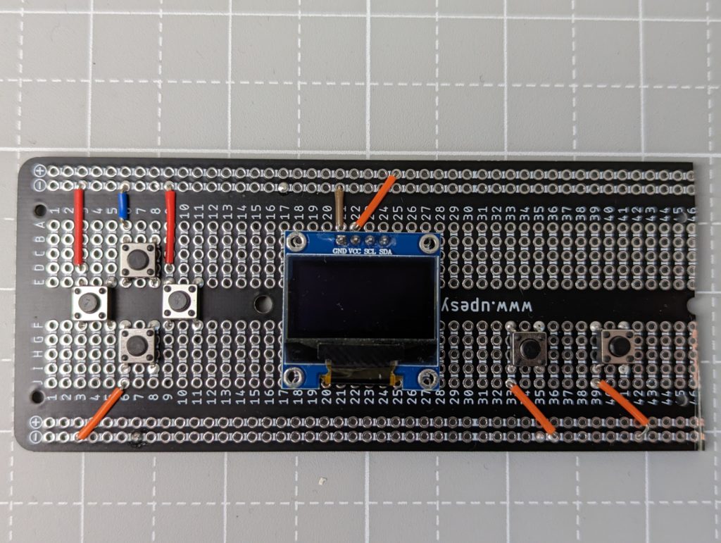
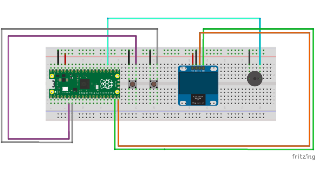
OK. Let’s start building our retro-gaming console by connecting a display to the Raspberry Pi Pico:
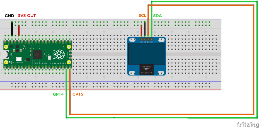
Before we can use the display, we must install the ssd1306 driver: Open the ssd1306.py file in Thonny and save it to the root directory of the Raspberry Pi Pico.
We first initialize I2C using pins GP14 and GP15. Then we initialize the OLED display.
from machine import Pin, I2C
from ssd1306 import SSD1306_I2C
import framebuf
import time

# Init I2C using pins GP14 & GP15
i2c = I2C(1, scl = Pin(15), sda = Pin(14), freq = 400000)

# Init oled display
WIDTH  = 128 # oled display width in pixels
HEIGHT = 64  # oled display height in pixels
oled = SSD1306_I2C(WIDTH, HEIGHT, i2c)
We can fill the screen with fill. We must call the method show() to make the change visible.
# Fill the screen
oled.fill(1)
oled.show()
To clear the screen, we fill it with zeroes:
oled.fill(0)
oled.show()
To draw pixels, we call the pixel method. The top left corner has coordinates (0,0) and the bottom right corner has coordinates (127,63)
oled.pixel(0, 0, 1)
oled.pixel(127, 63 , 1)
oled.show()
Let’s draw a line from the top left to the bottom right corner
oled.line(0, 0, 127, 63, 1)
oled.show()
A rectangle at coordinates X=32 and Y=48, with a width of 16 and a height of 4 pixels.
oled.rect(32, 48, 16, 4, 1)
oled.show()
We can fill the interior…
oled.fill_rect(32, 48, 16, 4, 1)
oled.show()
Display some text…
oled.text("YouMakeTech",8,8)
oled.show()
Make a vertical scrolling. Useful for shoot’em up!
# Vertical Scrolling
import random
for i in range(63):
    oled.scroll(0, 1) # scroll the screen down by one pixel
    oled.line(0, 0, 127, 0, 0) # fill the first row with black
    oled.pixel(random.randint(0,127), 0, 1) # display a random star on the first row
    oled.show()
    time.sleep(0.010)
And display images… Images are encoded with zeroes and ones. A one activates a pixel and a zero deactivates it.
To store images in memory, we use a byte array. Each byte contains 8 bits which can be either 0 or 1. From the byte array, we create a FrameBuffer object which provides methods to manipulate images. The blit method draws the image at the specified coordinates.
# Display an image
# Space Invaders sprite as array of 8x8 bits (= 8 bytes)
image = bytearray([0b00011000,
                   0b00111100,
                   0b01111110,
                   0b11011011,
                   0b11111111,
                   0b00100100,
                   0b01011010,
                   0b10100101])

# Load the image into a framebuffer (the image is 8x8)
fb = framebuf.FrameBuffer(image, 8, 8, framebuf.MONO_HLSB)

# Draw the image at coordinates X=96 and Y=0
oled.blit(fb, 96, 0)
oled.show()
Game programming on Raspberry Pi Pico | Pong
We know enough now to start coding a simple game of Pong!
Let’s start by drawing the ball. The x and y variables store the coordinates of the ball on the screen. The ball is a square of 4×4 pixels. To make the ball move, we write an infinite loop. With each iteration, we add the speeds vx and vy to the coordinates of the ball, clear the screen and draw the ball at the new coordinates:
from machine import Pin, I2C
from ssd1306 import SSD1306_I2C
import time

# Init I2C using pins GP14 & GP15
i2c = I2C(1, scl=Pin(15), sda=Pin(14), freq = 400000)

# Init oled display
WIDTH  = 128 # oled display width in pixels
HEIGHT = 64  # oled display height in pixels
oled = SSD1306_I2C(WIDTH, HEIGHT, i2c)

# Simple Pong
x = 64 # ball coordinates on the screen in pixels
y = 0
vx = 2 # ball velocity along x and y in pixels per frame
vy = 2
while True:
    # Clear the screen
    oled.fill(0)

    # Draw a 4x4 pixels ball at (x,y) in white
    oled.fill_rect(x, y, 4, 4, 1)
    oled.show()

    # Move the ball by adding the velocity vector
    x += vx
    y += vy
It’s all good but the ball leaves the screen! We have to bounce the ball when it hits the border:
while True:
    # Clear the screen
    oled.fill(0)

    # Draw a 4x4 pixels ball at (x,y) in white
    oled.fill_rect(x, y, 4, 4, 1)
    oled.show()

    # Move the ball by adding the velocity vector
    x += vx
    y += vy

    # Make the ball rebound on the edges of the screen
    if x < 0:
        x = 0
        vx = -vx
    if y < 0:
        y = 0
        vy = -vy
    if x + 4 > 128:
        x = 128 - 4
        vx = -vx
    if y + 4 > 64:
        y = 64 - 4
        vy = -vy
Pong game on Raspberry Pi Pico | Adding buttons to move the paddle
You can also display the paddle at the bottom of the screen. The paddle coordinates on the screen are stored in variables xp and yp. The paddle is a 16×4 pixels rectangle.
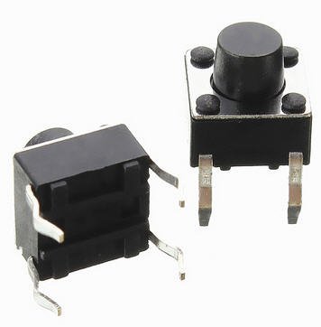
Let’s add 2 push buttons so that the player can move the paddle.
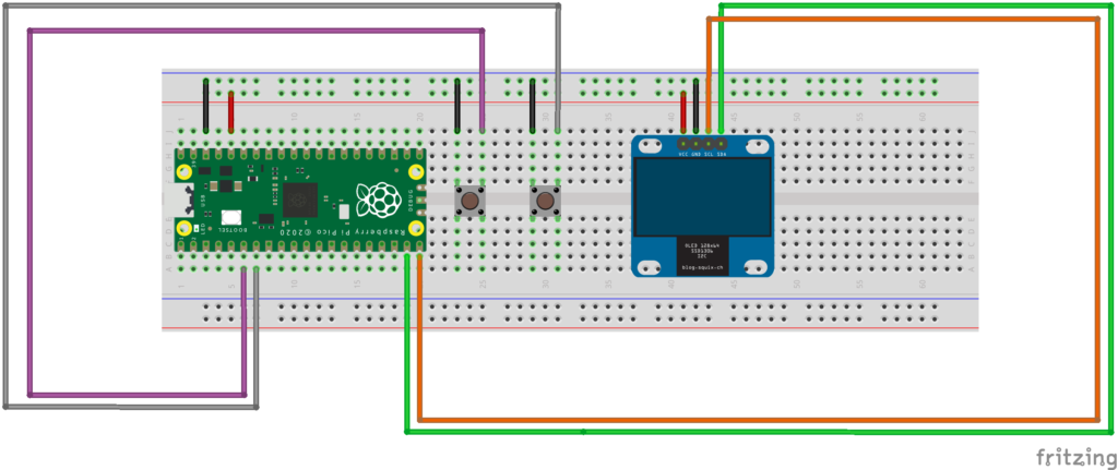
First, we import the Pin class from the machine module. The machine module is specific to MicroPython and allows to interact with the Raspberry Pi Pico hardware. To read a button state, we create a Pin object. IN means that the pin is an input, and PULL_UP specifies that when the button is not pressed, we would like the pin to report a value of 1.
The value method allows to read the state of the button:
– When the button is not pressed, the pin reports a value of 1
– When we press the button, we connect the pin to the GND and the pin reports a value of zero.
Let’s continue to code our Pong game. We would like to use the buttons to move the paddle left and right… In the game loop, we read the button states and change the position of the paddle accordingly.
from machine import Pin, I2C
from ssd1306 import SSD1306_I2C
import time

# Init I2C using pins GP14 & GP15
i2c = I2C(1, scl = Pin(15), sda = Pin(14), freq = 400000)

# Init oled display
WIDTH  = 128 # oled display width in pixels
HEIGHT = 64  # oled display height in pixels
oled = SSD1306_I2C(WIDTH, HEIGHT, i2c)

# Left and right push buttons connected to GP4 and GP5
left = Pin(4, Pin.IN, Pin.PULL_UP)
right = Pin(5, Pin.IN, Pin.PULL_UP)

# coordinates of the paddle on the screen in pixels
# the screen is 128 pixels wide by 64 pixel high
xp = 60
yp = 60

while True:
    # clear the screen
    oled.fill(0)

    # draw a 16x4 pixels paddle at coordinates (xp,yp)
    oled.fill_rect(xp, yp, 16, 4, 1)
    oled.show()

    if left.value() == 0:
        print("LEFT Button Pressed")
        xp = xp - 1 # Move the paddle to the left by 1 pixel
    elif right.value() == 0:
        print("RIGHT Button Pressed")
        xp = xp + 1 # Move the paddle to the right by 1 pixel

    time.sleep(0.001)
Our simple game of Pong is almost ready! Let’s add some sounds…
Making sounds with a piezo buzzer on Raspberry Pi Pico
To make sounds, we connect a piezo buzzer to pin GP18:
To make a sound, we will generate a fast on/off signal with something called PWM, or Pulse Width Modulation.
Specify the desired frequency and a duty cycle. To stop the sound, set the duty cycle to zero.
from machine import Pin, PWM
import time
# Passive piezo buzzer connected to pin GP18
buzzer = PWM(Pin(18))
# Play an A5 note (=440 Hz) for one second
buzzer.duty_u16(16384) # 16384 = 25% duty cycle
buzzer.freq(440) # A5 = 440 Hz
time.sleep(1)
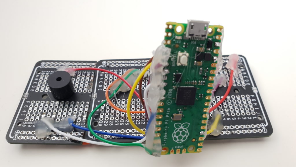
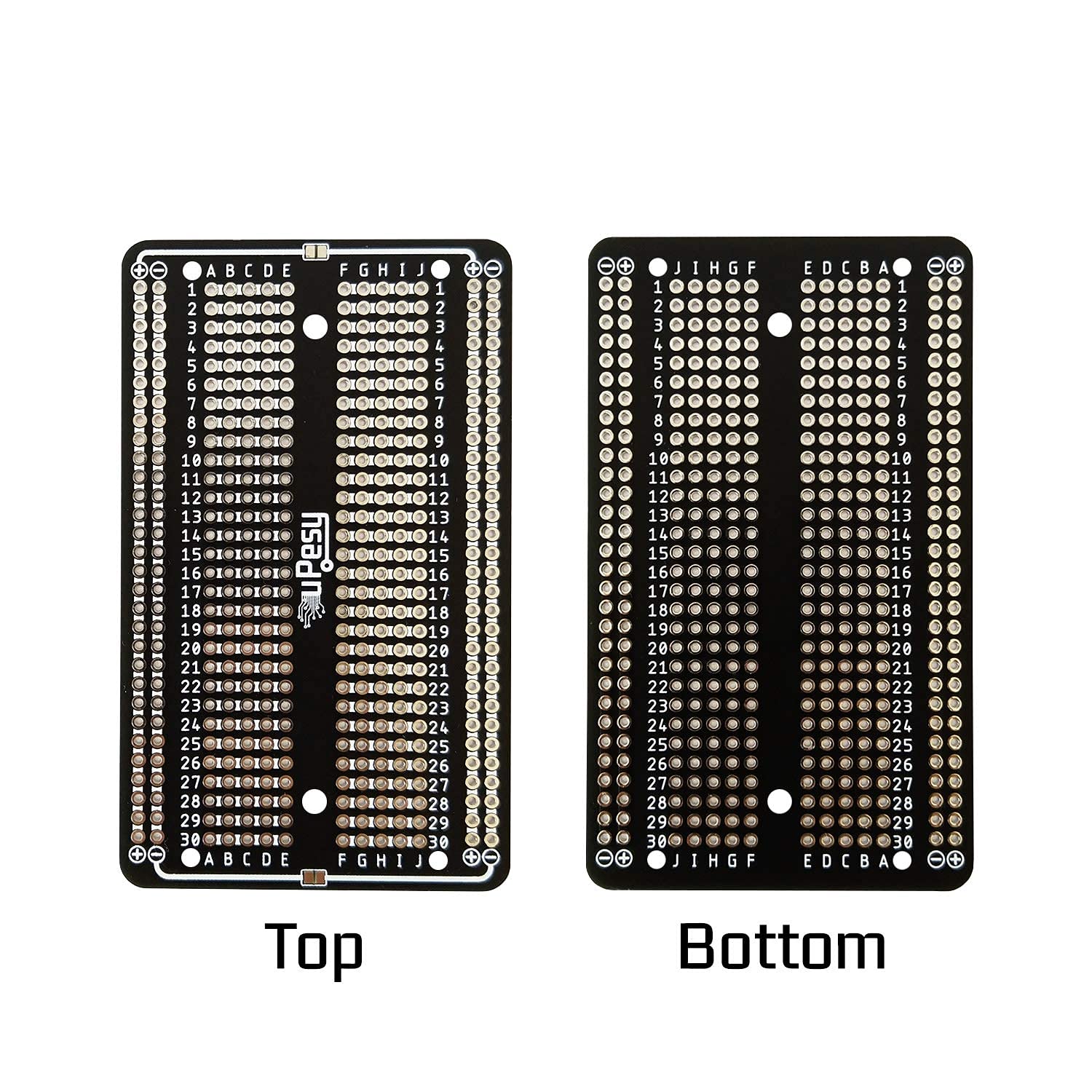
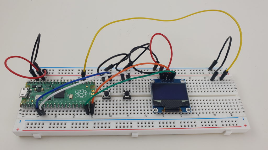
buzzer.duty_u16(0)Making the complete console
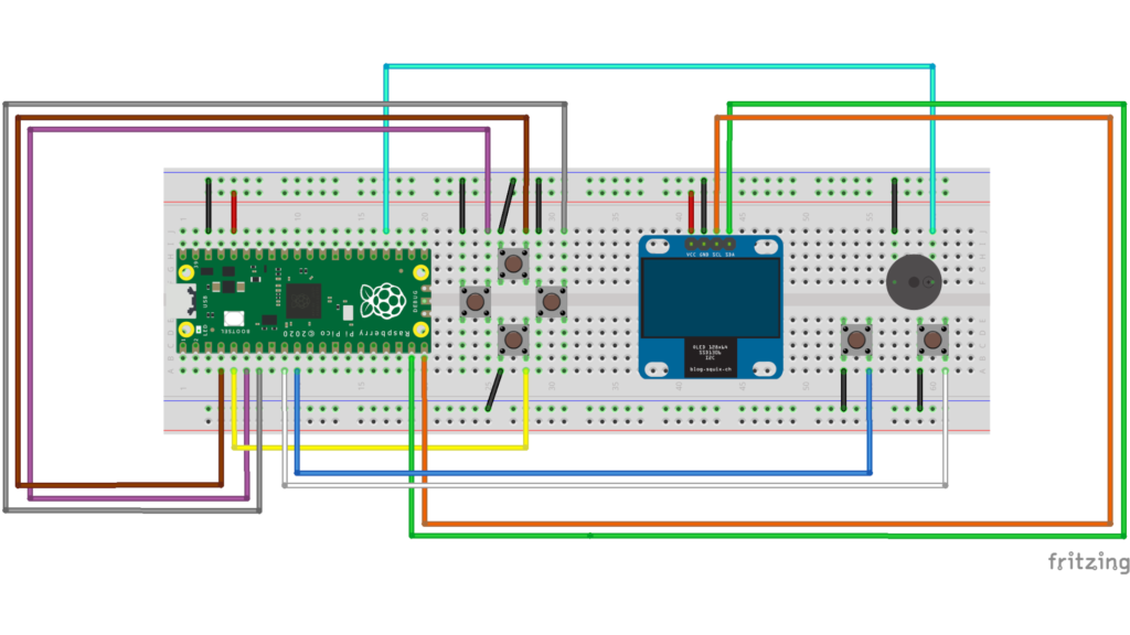
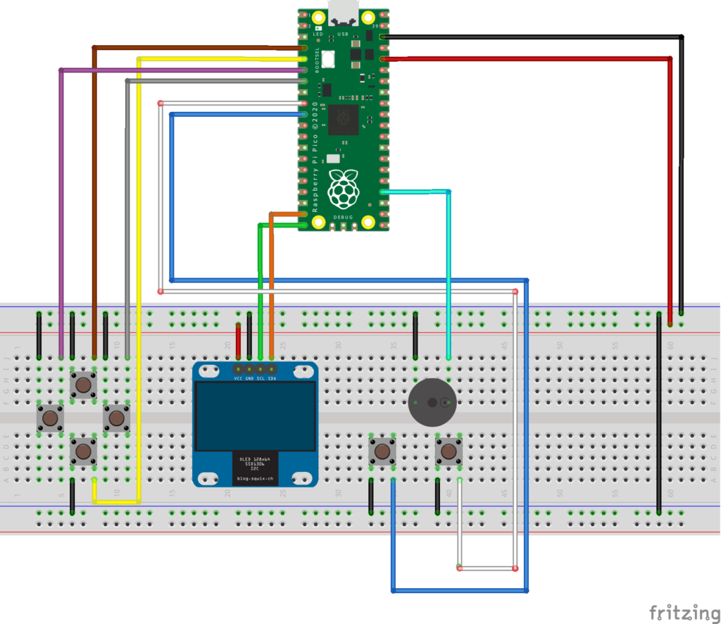
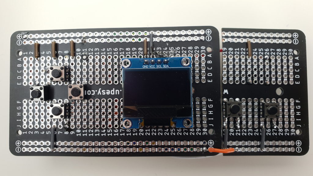
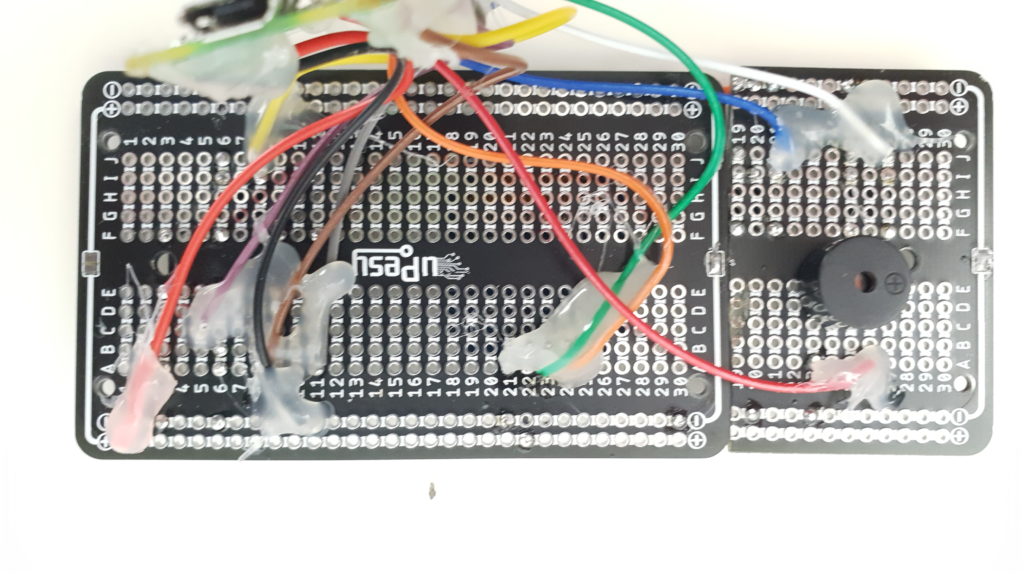
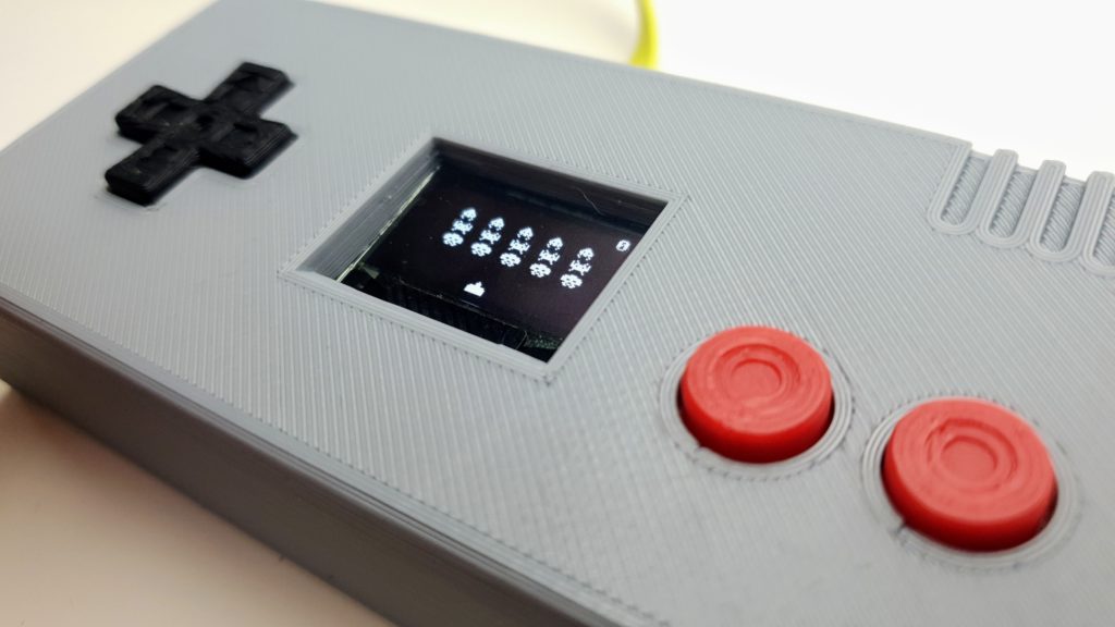
Now that we have a working prototype, with a screen, 2 buttons, and sound, we can build the complete console, with a solderable breadboard, a 3d printed case, and 6 buttons!